Contact
- +86 198 6184 4962
- jinanshixuxin@163.com
- +86 198 6184 4962
- Jibei Development Zone, Jinan City, Shandong Province, China
Hydraulic Cylinder
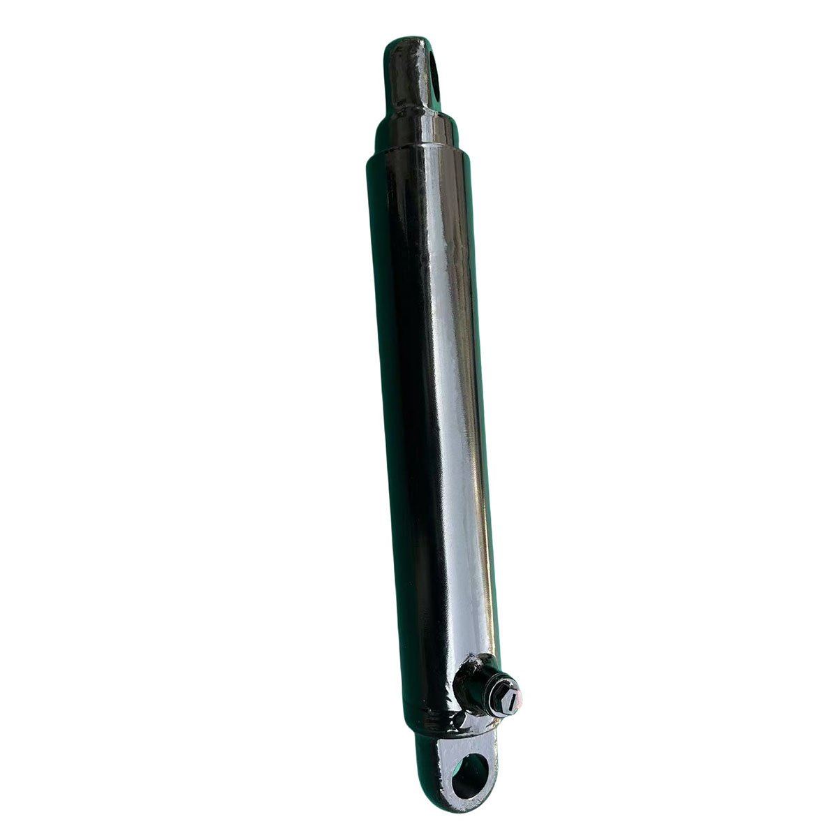
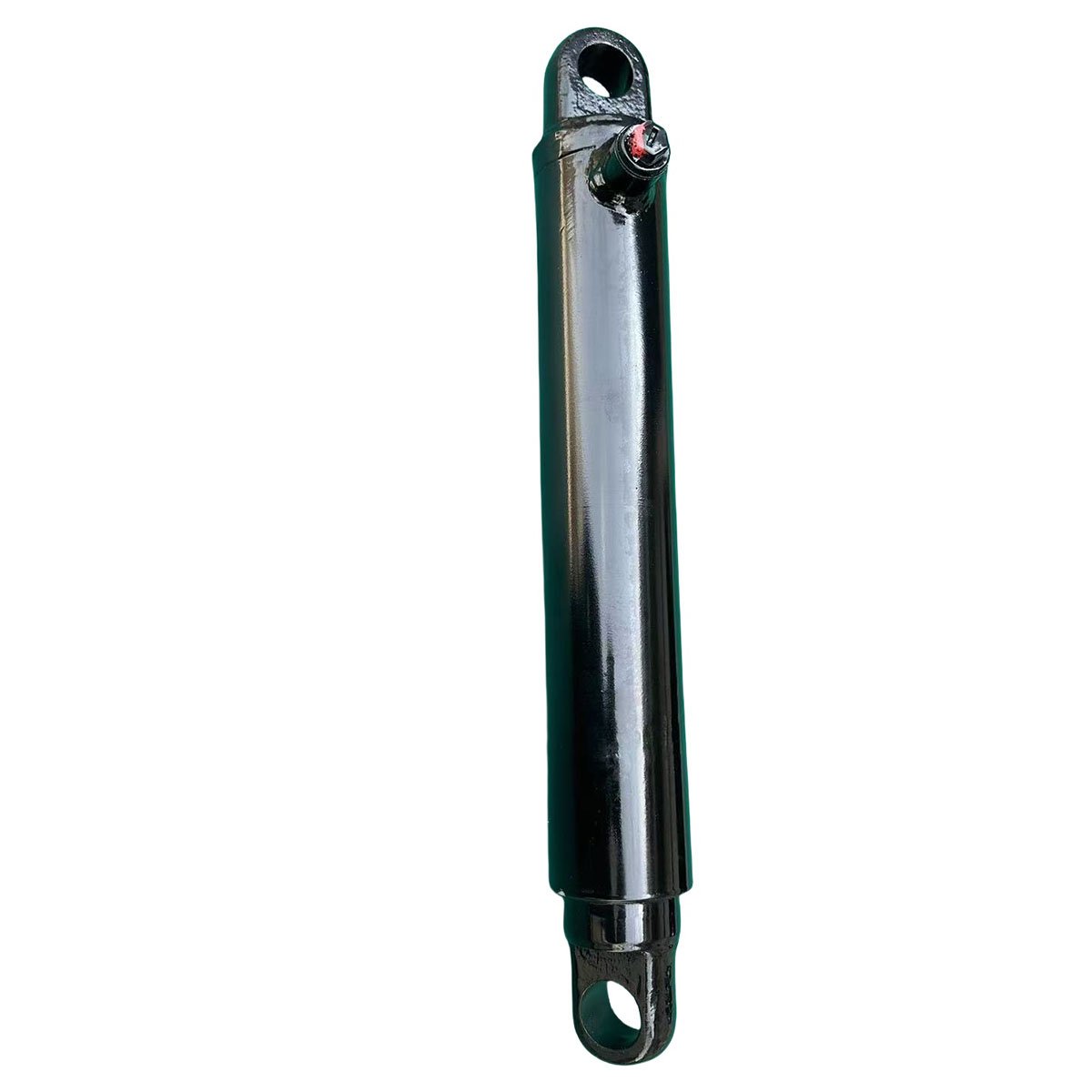
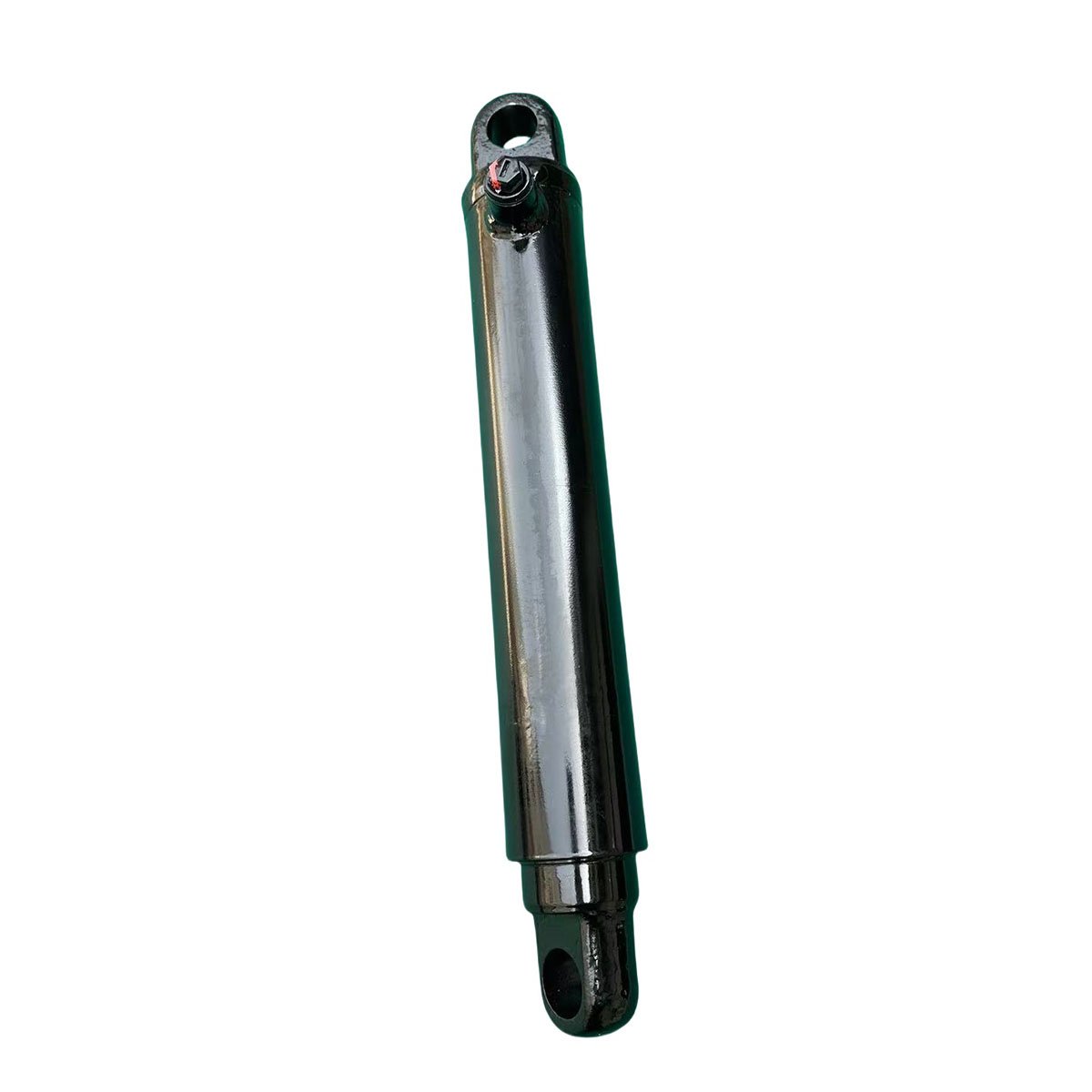
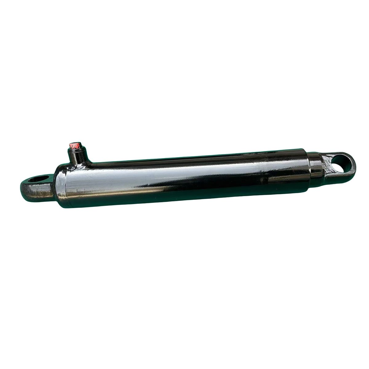
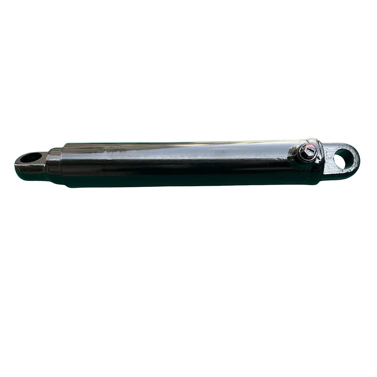
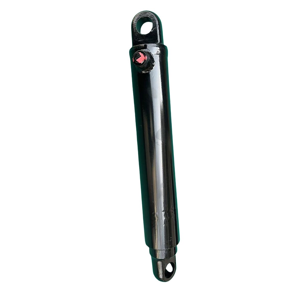
Engineered for robust performance, our hydraulic cylinder delivers precise linear motion with up to 4000 PSI pressure resistance. Constructed from high-strength alloy steel, the hard-chrome plated piston rod ensures minimal friction and corrosion protection, while dual-seal technology eliminates leaks for reliable operation. Versatile in design, it adapts to bore sizes 1.5–10 inches and stroke lengths up to 100 inches, handling 5–150-ton loads across construction, mining, and manufacturing. Lightweight yet durable, it powers excavators, presses, and material handlers with efficient lifting/pushing capabilities, backed by quick-install compatibility and low-maintenance design.
- jinanshixuxin@163.com
- A3N1A3

Description
Hydraulic Cylinder: Product Description
Overview
A hydraulic cylinder is a mechanical actuator that converts hydraulic energy into linear motion and force. It consists of a cylindrical barrel, a piston connected to a rod, and end caps with ports for hydraulic fluid entry/exit. Widely used in industrial machinery, construction equipment, automotive systems, and aerospace, it enables precise control of movement and heavy-load manipulation.
Key Components & Structure
- Cylinder Barrel: A high-strength steel tube with inner surface precision-finished to ensure smooth piston movement and prevent fluid leakage.
- Piston: Seals the barrel and divides it into two chambers (rod and cap ends), driven by hydraulic pressure.
- Piston Rod: Extends/retracts from the barrel, transmitting force to the load; often chrome-plated for corrosion resistance.
- End Caps: Secure the barrel ends, containing ports for fluid connection and guiding the piston rod.
- Seals & Packings: Prevent hydraulic fluid leakage and protect internal components from contaminants.
Working Principle
Hydraulic fluid (e.g., oil) is pumped into one chamber of the cylinder, creating pressure that pushes the piston and rod. The fluid in the opposite chamber is discharged back to the reservoir, enabling linear motion. The force generated is calculated by:
- Force (F) = Pressure (P) × Piston Area (A)
Adjusting fluid pressure or piston diameter controls the output force, while flow rate regulates speed.
Key Technical Parameters
- Bore Diameter: Determines force capacity (e.g., 50 mm to 300 mm).
- Stroke Length: Maximum extension of the piston rod (e.g., 100 mm to 5,000 mm).
- Working Pressure: Typically 100 bar to 350 bar; high-pressure models reach 700 bar.
- Temperature Range: -20°C to 120°C (dependent on fluid and seal materials).
- Mounting Style: Flange, clevis, trunnion, or foot-mounted for installation flexibility.
Advantages
- High Force Output: Capable of generating thousands of newtons for heavy-duty tasks.
- Precise Control: Adjustable speed and force via hydraulic system parameters.
- Durability: Robust design withstands harsh environments and prolonged use.
- Compact Design: Offers high power density compared to mechanical alternatives.
Get the latest price? We will reply as soon as possible (within 12 hours)
Related products
-
Hydro-Cylinder
Freight elevator hydraulic power unit -
Lift Power Unit
Freight elevator hydraulic power unit -
Freight elevator pump station
Freight elevator hydraulic power unit -
Freight Elevator Pump Station
Freight elevator hydraulic power unit